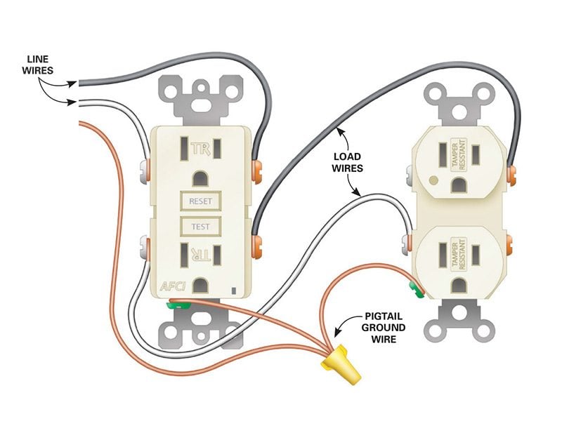
Wiring Outlets Diagram are crucial tools for understanding the electrical connections in a building or structure. These diagrams provide a visual representation of how outlets are wired and connected to the electrical system, helping electricians and homeowners alike to ensure safe and efficient electrical installations.
Why Wiring Outlets Diagram are essential
- Helps to plan and design electrical installations
- Aids in troubleshooting electrical issues
- Ensures compliance with electrical codes and regulations
- Improves safety by preventing electrical hazards
How to read and interpret Wiring Outlets Diagram effectively
When looking at a Wiring Outlets Diagram, it is important to pay attention to the following key elements:
- Outlet locations and types
- Wire colors and connections
- Circuit breakers or fuses associated with each outlet
- Grounding and bonding connections
How Wiring Outlets Diagram are used for troubleshooting electrical problems
Wiring Outlets Diagram can be invaluable when trying to diagnose and fix electrical issues. By following the diagram, you can easily identify the source of the problem and take appropriate action. Common uses of Wiring Outlets Diagram for troubleshooting include:
- Identifying loose or damaged connections
- Checking for overloaded circuits
- Verifying correct wiring configurations
- Locating faulty outlets or switches
Importance of safety when working with electrical systems
When working with electrical systems and using Wiring Outlets Diagram, safety should always be the top priority. Here are some essential safety tips to keep in mind:
- Turn off the power before working on any electrical components
- Use insulated tools and equipment to prevent electric shock
- Avoid working in wet or damp conditions
- Follow all safety guidelines and regulations
Wiring Outlets Diagram
How to Wire an Outlet and Add an Electrical Outlet (DIY) | Family Handyman

A Comprehensive Guide To Gfci Outlet Wiring Diagrams – Wiring Diagram

how to wire multiple outlets together – Wiring Work
/wiring-electrical-receptacle-circuits-through-a-receptacle-1152787-01-2a9a43dca2d04d6597dcfb791a548ff9.jpg?strip=all)
WIRING DIAGRAM FOR MULTIPLE OUTLET – YouTube

Wiring A Light Switch And Outlet Together Diagram – Diysium

How to Install Electrical Outlets in the Kitchen | The Family Handyman
