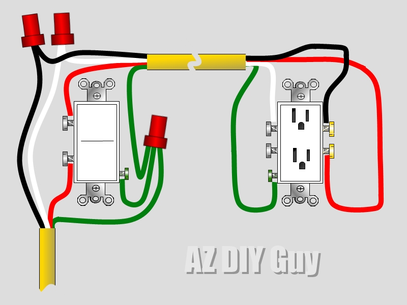
Receptacle Wiring Diagram Made Simple are an essential tool for anyone working with electrical systems. These diagrams provide a visual representation of how electrical outlets are wired in a building, making it easier to understand and troubleshoot any issues that may arise.
Why are Receptacle Wiring Diagram Made Simple Essential?
- Ensure proper installation of electrical outlets
- Aid in troubleshooting electrical problems
- Comply with electrical codes and regulations
- Prevent electrical hazards and accidents
How to Read and Interpret Receptacle Wiring Diagram Made Simple Effectively
When looking at a receptacle wiring diagram, it’s important to understand the symbols and markings used. Here are some tips to help you read and interpret these diagrams:
- Identify the different components of the diagram, such as wires, outlets, and switches
- Follow the flow of electricity from the breaker box to the outlets
- Pay attention to the color-coding of wires and their corresponding functions
- Refer to the legend or key for any symbols you are not familiar with
Using Receptacle Wiring Diagram Made Simple for Troubleshooting
Receptacle wiring diagrams can be a valuable tool for troubleshooting electrical problems in a building. By following the diagram and tracing the flow of electricity, you can pinpoint any issues and make the necessary repairs. Here are some common problems that can be identified using these diagrams:
- Loose connections
- Short circuits
- Grounding issues
- Overloaded circuits
It’s important to always prioritize safety when working with electrical systems and using wiring diagrams. Here are some safety tips and best practices to keep in mind:
- Turn off the power before working on any electrical components
- Use insulated tools to prevent electric shock
- Avoid working in wet or damp conditions
- Double-check your work before restoring power
Receptacle Wiring Diagram Made Simple
Electric Receptacle Wiring Diagram

Electrical Basic Wiring Diagram

Wiring Diagram Electrical Outlet – Wiring Digital and Schematic
/wiring-electrical-receptacle-circuits-through-a-receptacle-1152787-01-2a9a43dca2d04d6597dcfb791a548ff9.jpg?strip=all)
Receptacle Wiring Diagram Examples – Wiring Flow Schema

Wiring Up A Receptacle

How to Install Electrical Outlets in the Kitchen (Step-By-Step) (DIY)
