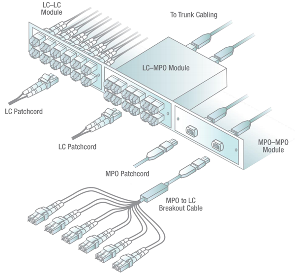
Understanding Patch Panel Wiring Diagram is crucial for anyone working with electrical systems. A Patch Panel Wiring Diagram is a visual representation of the connections between various components in an electrical system. This diagram helps technicians and electricians to understand how the system is wired and how different components are interconnected.
Importance of Patch Panel Wiring Diagram
- Ensures proper installation of electrical components
- Aids in troubleshooting electrical issues
- Facilitates maintenance and repairs
- Improves overall safety of the electrical system
Reading and Interpreting Patch Panel Wiring Diagram
When reading a Patch Panel Wiring Diagram, it is essential to understand the symbols and labels used in the diagram. Each component is represented by a specific symbol, and the connections between components are shown by lines. It is important to follow the lines and connections carefully to ensure proper installation and functioning of the electrical system.
Using Patch Panel Wiring Diagram for Troubleshooting
Patch Panel Wiring Diagrams are valuable tools for troubleshooting electrical problems. By referring to the diagram, technicians can identify the source of the issue and locate the faulty component or connection. This saves time and effort in diagnosing and fixing electrical problems.
Importance of Safety
When working with electrical systems and using wiring diagrams, it is crucial to prioritize safety. Here are some safety tips and best practices to follow:
- Always turn off the power before working on electrical systems.
- Use insulated tools and equipment to prevent electric shock.
- Wear appropriate personal protective equipment, such as gloves and safety goggles.
- Follow proper procedures and guidelines for working with electrical systems.
- Double-check connections and wiring before energizing the system.
Patch Panel Wiring Diagram
Patch Panel Wiring Guide
Rj45 Patch Panel Wiring Diagram – Organicify

How To Use a Fiber Optic Patch Panel – Teleweaver

Patch Panels: A Complete Guide

[DIAGRAM] 110 Patch Panel Wiring Diagram – MYDIAGRAM.ONLINE
![Patch Panel Wiring Diagram [DIAGRAM] 110 Patch Panel Wiring Diagram - MYDIAGRAM.ONLINE](https://i1.wp.com/i.stack.imgur.com/JvaKo.jpg)
How to Create a Patch Panel Wiring Diagram: Step-by-Step Example
