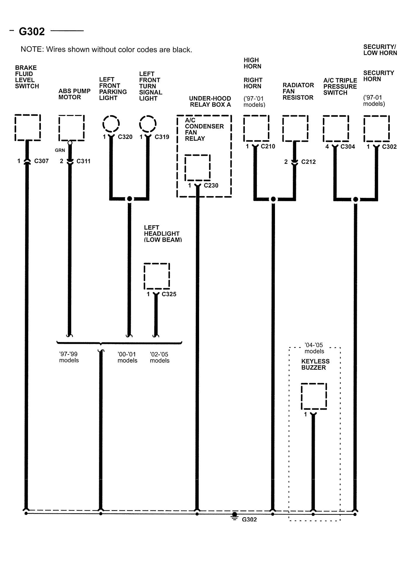
When it comes to diagnosing and troubleshooting electrical problems in a vehicle, having access to an Ecu Wiring Diagram can be incredibly valuable. An ECU (Engine Control Unit) wiring diagram provides a detailed outline of the electrical connections and wiring within the vehicle’s ECU system. This diagram is essential for understanding how various components are interconnected and how electrical signals flow throughout the system.
Importance of Ecu Wiring Diagrams
- Helps identify the location of specific components within the ECU system
- Shows the electrical connections between different components
- Provides information on wire colors and pin configurations
- Aids in diagnosing electrical issues and troubleshooting problems
Reading and Interpreting Ecu Wiring Diagrams
Reading an ECU wiring diagram may seem intimidating at first, but with a little practice, it can become a valuable tool for any mechanic. Here are some tips for effectively interpreting ECU wiring diagrams:
- Start by familiarizing yourself with the symbols and abbreviations used in the diagram
- Follow the flow of the electrical connections from one component to another
- Pay attention to wire colors, pin numbers, and connector locations
- Use a highlighter or colored pencils to mark important connections or circuits
Using Ecu Wiring Diagrams for Troubleshooting
ECU wiring diagrams are invaluable when it comes to troubleshooting electrical problems in a vehicle. By following the wiring diagram and understanding how the components are connected, you can easily identify potential issues and pinpoint the source of the problem. Here are some ways ECU wiring diagrams can be used for troubleshooting:
- Locating faulty connections or broken wires
- Identifying short circuits or open circuits within the system
- Testing sensors and actuators for proper operation
- Verifying power and ground connections to the ECU system
Importance of Safety
Working with electrical systems can be dangerous if proper safety precautions are not followed. When using ECU wiring diagrams or working on the electrical system of a vehicle, it is important to prioritize safety. Here are some safety tips to keep in mind:
- Always disconnect the battery before working on the electrical system
- Use insulated tools to prevent electrical shocks
- Avoid working on the electrical system in wet or damp conditions
- Double-check all connections and wiring before reassembling the system
Ecu Wiring Diagram
Complete Guide: 2001 Honda Civic ECU Wiring Diagram for Easy

4afe Ecu Wiring Diagram – Wiring Diagram

02 Wrx Jdm Ecu Wiring Diagram

2005 C230 Ecu Wiring Diagram

Ecu Wiring Diagram – Headcontrolsystem

Rx8 Ecu Wiring Diagram
