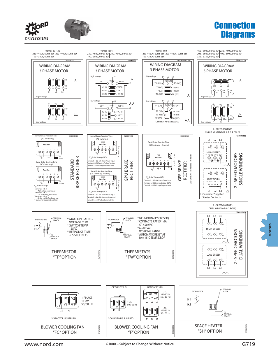
Brake Motor Wiring Diagrams are essential tools for mechanics and technicians working on electrical systems in vehicles or machinery. These diagrams provide a visual representation of the wiring connections and layout for the brake motor, allowing for easier troubleshooting and maintenance.
Why are Brake Motor Wiring Diagrams Essential?
Brake Motor Wiring Diagrams are essential for a number of reasons:
- They provide a detailed overview of the electrical connections in the brake motor system.
- They help identify the components and their respective wiring connections.
- They assist in diagnosing and troubleshooting electrical issues.
- They ensure proper installation and maintenance of the brake motor system.
How to Read and Interpret Brake Motor Wiring Diagrams
Reading and interpreting Brake Motor Wiring Diagrams can be made easier by following these steps:
- Identify the key components in the diagram, such as the motor, brake, power source, and control circuits.
- Follow the wiring lines to trace the connections between the components.
- Refer to the legend or key provided in the diagram for symbols and color codes.
- Pay attention to the direction of the flow of electricity and the sequence of connections.
Using Brake Motor Wiring Diagrams for Troubleshooting
Brake Motor Wiring Diagrams are incredibly useful for troubleshooting electrical problems in the brake motor system. Here’s how you can effectively use them:
- Identify the specific issue or malfunction in the system based on symptoms or error codes.
- Refer to the wiring diagram to locate the components related to the issue.
- Check for loose connections, damaged wires, or faulty components based on the diagram.
- Follow the wiring diagram to test the continuity of circuits and diagnose the root cause of the problem.
Safety Tips when Working with Brake Motor Wiring Diagrams
When working with electrical systems and using wiring diagrams, it’s crucial to prioritize safety. Here are some safety tips and best practices to keep in mind:
- Always disconnect the power source before working on the electrical system.
- Use insulated tools and equipment to prevent electrical shocks.
- Avoid working on wet or damp surfaces to reduce the risk of electrical hazards.
- Double-check your connections and follow proper wiring practices to avoid short circuits or fires.
Brake Motor Wiring Diagram
Engine Brake Wiring Diagram – Wiring Diagram and Schematics

Clutch Brake Motor Connection Diagram Rectifier Module – YouTube

Motor brake rectifier connection diagram | Engineers CommonRoom

A Guide on How to Wire a Sew Brake Motor: Step-by-Step Diagram

brake motor wiring diagram
Nord Brake Motor Wiring Diagram – Coearth
