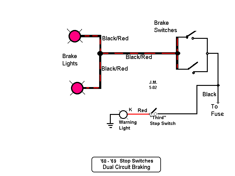
Brake Light Switch Wiring Diagrams are essential tools for mechanics and DIY enthusiasts alike when it comes to understanding the electrical systems of vehicles. These diagrams provide a visual representation of how the brake light switch is wired in a vehicle, helping users identify connections, components, and potential issues.
Why Brake Light Switch Wiring Diagrams are essential
Brake Light Switch Wiring Diagrams are crucial for several reasons:
- They help in understanding the circuit layout and connections of the brake light switch.
- They assist in diagnosing and troubleshooting electrical issues related to the brake lights.
- They provide a reference point for making modifications or repairs to the wiring system.
Reading and interpreting Brake Light Switch Wiring Diagrams
When reading a Brake Light Switch Wiring Diagram, it is important to:
- Identify the components such as the brake light switch, wires, connectors, and fuses.
- Follow the flow of the circuit from the power source to the brake lights.
- Understand the symbols and color codes used in the diagram to represent different components.
Using Brake Light Switch Wiring Diagrams for troubleshooting
Brake Light Switch Wiring Diagrams can be used effectively for troubleshooting electrical problems by:
- Checking for continuity in the wiring to ensure there are no breaks or shorts.
- Testing the voltage at different points in the circuit to identify any power issues.
- Comparing the actual wiring in the vehicle with the diagram to spot any discrepancies.
Importance of safety when working with electrical systems
When working with electrical systems and using wiring diagrams, it is crucial to prioritize safety. Some tips and best practices include:
- Always disconnect the battery before working on any electrical components to avoid the risk of electric shock.
- Use insulated tools and wear protective gear such as gloves and safety goggles.
- Double-check all connections and wiring before reassembling the components to prevent short circuits.
Brake Light Switch Wiring Diagram
Brake Light Switch Circuit Wiring Diagram

Basic Brake Light Switch Wiring Diagram

The Ultimate Guide: E36 Brake Light Switch Wiring Diagram

️1996 Chevy Silverado Brake Light Switch Wiring Diagram Free Download

[DIAGRAM] Fj Cruiser For Brake Light Switch Wiring Diagram – MYDIAGRAM
![Brake Light Switch Wiring Diagram [DIAGRAM] Fj Cruiser For Brake Light Switch Wiring Diagram - MYDIAGRAM](http://www.thumpertalk.com/uploads/monthly_09_2014/post-198959-0-87748100-1410466744.jpg)
Brake Light Circuit Diagram
