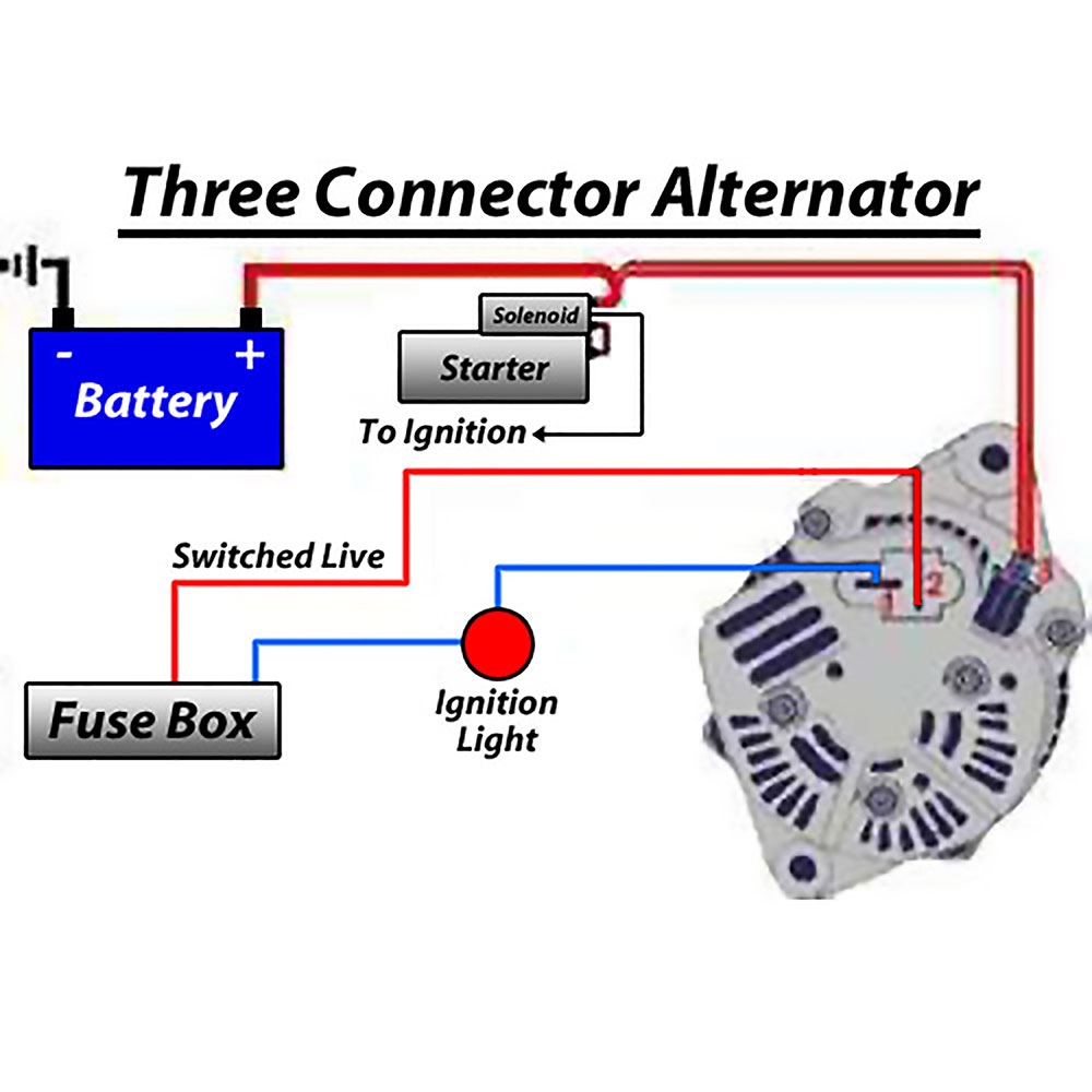
Basic Alternator Wiring Diagrams are essential tools for anyone working on automotive electrical systems. These diagrams provide a clear visual representation of the wiring connections and components involved in the alternator system, helping mechanics troubleshoot and repair any issues that may arise.
Why Basic Alternator Wiring Diagrams are essential
Basic Alternator Wiring Diagrams are essential for several reasons:
- They provide a clear visual representation of the wiring connections and components in the alternator system.
- They help mechanics understand how the electrical system works and how different components are connected.
- They are essential for troubleshooting electrical issues and identifying faulty components.
How to read and interpret Basic Alternator Wiring Diagrams effectively
Reading and interpreting Basic Alternator Wiring Diagrams can be daunting for beginners, but with a little practice, it becomes easier. Here are some tips to help you read and interpret these diagrams effectively:
- Start by familiarizing yourself with the symbols and colors used in the diagram.
- Follow the flow of the wiring diagram from the power source to the components and back to the ground.
- Pay attention to the connections between components and any switches or relays in the system.
Using Basic Alternator Wiring Diagrams for troubleshooting electrical problems
Basic Alternator Wiring Diagrams are invaluable tools for troubleshooting electrical problems in automotive systems. Here’s how you can use them effectively:
- Identify the specific problem you are experiencing and locate the corresponding section of the wiring diagram.
- Check for continuity and voltage at different points in the system to pinpoint the issue.
- Compare the actual wiring connections to the diagram to identify any discrepancies.
When working with Basic Alternator Wiring Diagrams, it is crucial to prioritize safety at all times. Here are some safety tips and best practices to keep in mind:
- Always disconnect the battery before working on any electrical system to prevent short circuits and electrical shocks.
- Use insulated tools and wear appropriate safety gear, such as gloves and safety glasses, when working with wiring diagrams.
- Double-check all connections before reassembling the system to ensure everything is properly connected and secure.
Basic Alternator Wiring Diagram
Simple 12v Alternator Wiring Diagram

Alternator Circuit Explained : 12 Volt Alternator Wiring Diagram

[2 Wire, 3 Wire, and 4 Wire] Alternator Wiring Diagram – Drill and Driver
![Basic Alternator Wiring Diagram [2 Wire, 3 Wire, and 4 Wire] Alternator Wiring Diagram - Drill and Driver](https://i1.wp.com/www.drillanddriver.com/wp-content/uploads/2022/12/4-wire-alternator-wiring-diagram-2.jpg)
inside my 01 honda alternator diagram – Wiring Flow Line

Basic Alternator Wiring Diagram | Hastalavista – Alternator Wiring

Simple 3 Wire Alternator Wiring Diagram
