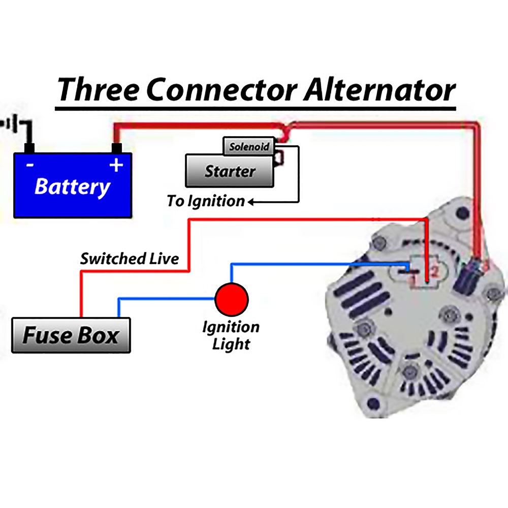
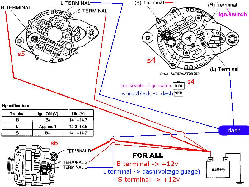
When it comes to understanding the electrical system of a vehicle, the alternator wiring schematic is a crucial component. This schematic diagram provides a detailed overview of how the alternator is wired to the rest of the vehicle’s electrical system, including the battery, starter, and various other components. By understanding the alternator wiring schematic, mechanics and DIY enthusiasts can troubleshoot electrical issues, make repairs, and ensure the proper functioning of the vehicle’s electrical system.
Why Alternator Wiring Schematic are essential
The alternator wiring schematic is essential for several reasons:
- It helps identify the wiring connections between the alternator and other electrical components.
- It provides a visual representation of the electrical system, making it easier to understand how the system works.
- It serves as a reference guide for troubleshooting electrical issues and making repairs.
How to read and interpret Alternator Wiring Schematic effectively
Reading and interpreting an alternator wiring schematic may seem daunting at first, but with practice and the right approach, it can become second nature. Here are some tips for effectively understanding alternator wiring schematics:
- Start by familiarizing yourself with the symbols and abbreviations used in the schematic.
- Follow the flow of the wiring diagram from the alternator to other components, noting the connections and pathways.
- Pay attention to color-coding and labeling to identify different wires and their functions.
How Alternator Wiring Schematic are used for troubleshooting electrical problems
Alternator wiring schematics are invaluable tools for troubleshooting electrical problems in a vehicle. By referencing the schematic diagram, mechanics can:
- Identify faulty connections or wires that may be causing electrical issues.
- Check for continuity and proper voltage levels in the wiring system.
- Trace the source of electrical problems back to the alternator or other components.
Importance of safety when working with electrical systems
When working with electrical systems and using wiring diagrams, safety should always be the top priority. Here are some safety tips and best practices to keep in mind:
- Always disconnect the battery before working on the electrical system to prevent electrical shocks or short circuits.
- Use insulated tools and wear protective gear, such as gloves and goggles, to prevent injuries.
- Double-check all connections and wiring before reassembling the system to ensure everything is properly connected.
Alternator Wiring Schematic
Common Delco SI Series Alternator Wiring Diagram | Smith Co Electric

Alternator Wiring Diagram For The Battery Alternator Car – Floyd Wired

Alternator Circuit Explained : 12 Volt Alternator Wiring Diagram

Wiring An Alternator Diagram

Alternator To Motor Wiring Diagram

Alternator Wiring Diagram Bosch
