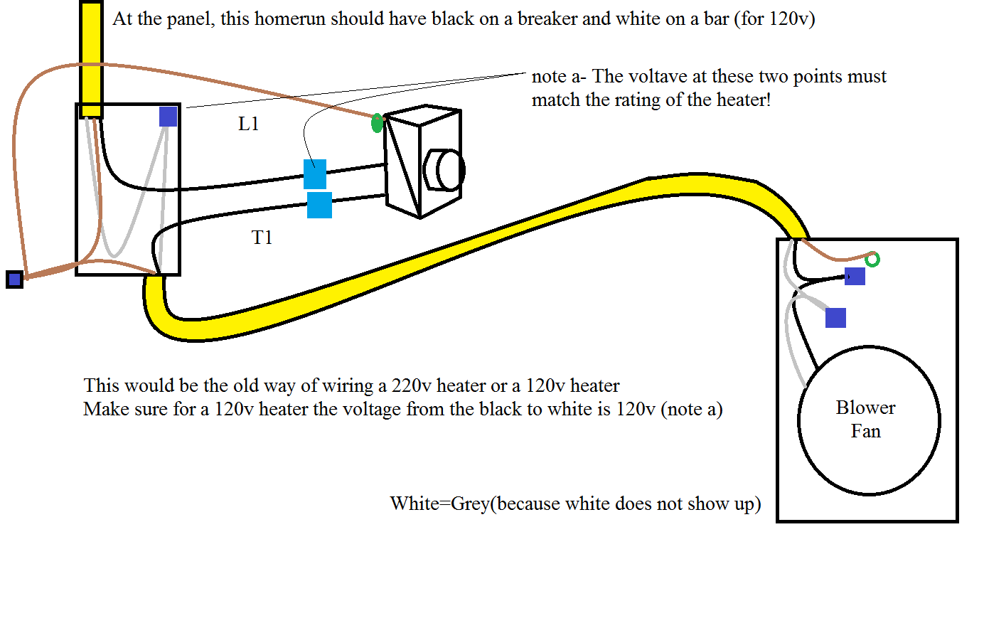
When dealing with electrical systems, having a clear and accurate wiring diagram is crucial. In this article, we will delve into the world of 120v Motor Wiring Diagrams, exploring their importance, how to read and interpret them effectively, and how they can be used for troubleshooting electrical problems.
Why are 120v Motor Wiring Diagrams Essential?
120v Motor Wiring Diagrams are essential for a variety of reasons:
- They provide a visual representation of the electrical system, showing how all the components are connected.
- They help ensure that the motor is wired correctly, preventing potential damage or malfunctions.
- They serve as a reference point for future maintenance or repairs, making it easier to identify and address any issues that may arise.
Reading and Interpreting 120v Motor Wiring Diagrams
Reading and interpreting 120v Motor Wiring Diagrams may seem daunting at first, but with some guidance, it can become second nature:
- Start by identifying the key components of the diagram, such as the motor, power source, and any control devices.
- Follow the lines and symbols to trace the flow of electricity throughout the system.
- Pay attention to labels and color codes to differentiate between different wires and connections.
Using 120v Motor Wiring Diagrams for Troubleshooting
When faced with electrical problems, 120v Motor Wiring Diagrams can be invaluable tools for troubleshooting:
- Compare the actual wiring of the motor to the diagram to identify any discrepancies or faults.
- Use a multimeter to test for continuity and voltage at various points in the circuit, referring to the diagram for guidance.
- Isolate and repair any faulty connections or components based on the information provided in the diagram.
Importance of Safety
It is crucial to prioritize safety when working with electrical systems and using wiring diagrams:
- Always disconnect power sources before working on any electrical components to prevent the risk of electric shock.
- Use insulated tools and equipment to avoid accidental contact with live wires.
- Double-check all connections and wiring before turning the power back on to ensure everything is properly secured and aligned.
120v Motor Wiring Diagram
Step-by-Step Guide: How to Wire a 120v Motor – Wiring Diagram Included

Single Phase Motor Wiring Diagrams 120 Volt

Step-by-Step Guide: How to Wire a 120v Motor – Wiring Diagram Included

120v Blower Motor Wiring Diagram

120v Ac Capacitor Motor Reversing Switch Wiring Diagram

120v Motor Wiring Diagram – Wiring Diagram and Schematic
